PACS: 61.46.Df
Новый подход в метрологии в нанообласти
С.К. Максимов1, К.С.Максимов2
1 Московский государственный институт электронной техники
2АНО «Аналитика и высокие технологии»
E-mail адрес автора, ответственного за переписку: E-mail: email hidden; JavaScript is required
Аннотация. Даны представления о пофракционном методе контроля в нанообласти и описана ключевая стадия метода, связанная с определением формы и размеров нанообъектов по РЭМ изображениям, полученным при разных сходимостях электронного зонда.
Свойства нанообъектов определяет триада: размер-структура-огранка, контроль которой необходим и в свете их функциональных характеристик [1], и в свете их совместимости с биосферой [2]. Не существует технологий, позволяющих получать массивы с нанообъектами одного размера и (из-за зависимости между размерами, структурой и огранкой) с одним набором структурно-морфологических характеристик [3-7]. Неконтролируемые объекты негативно сказывается на работе приборов и опасны, поскольку вызывают нарушения метаболизма в живых организмах [1,2]. Выходной контроль должен основываться на выделении фракций с разными структурой и морфологией, а экологическая безопасность требует идентификации фракций, доля которых составляет 10-5 – 10-7 от общей массы объектов [4-7]. Нанотехнологии, обеспечивающие оптимизацию свойств объектов и безопасность для биосферы, возможны только, если будет решена проблема выходного контроля [2,4-7], но контроль формы и структуры наночастиц это прерогатива микроскопических методов. Однако лишь растровая электронная микроскопии (РЭМ) позволяет контролировать массивы с числом нанообъектов ³ 106. При фиксированных условиях формирования РЭМ изображений их размеры, форма и распределения интенсивности определяются параметрами изображаемых объектов [8,9], и пофракционный контроль может базироваться на распределении изображений с близкими характеристиками по группам. Для разделения на фракции необходимо определять причины вариаций этих характеристик, но в РЭМ нет методов характеризации объектов с априори неизвестными габитусами и вариациями состава [8,9]. Необходимо «научить» РЭМ контролировать форму и размеры нанообъектов.
РЭМ изображения возникают при сканировании электронного зонда по поверхности объекта и представляют собой сумму электронов отдачи, генерируемых объектом в ответ на процесс неупругого рассеяния электронов зонда или пробы, (проба – сечение зонда поверхностью объекта). РЭМ изображения отражают два фактора. Проба при движении по поверхности объекта выходит за его контур, и на распределение электронов отдачи, эмитированных объектом, накладывается распределение электронов, эмитируемых подложкой. Выход электронов отдачи возрастает, если он происходит через пересекающиеся поверхности. Поэтому РЭМ изображения искаженно отражают объект, на них невозможно указать точки, отвечающие его краям, и напрямую определить его размеры [8,9].
Размер сфокусированной пробы в РЭМ приближается к »1,0 nm, но даже подобные РЭМ не решают проблему характеризации нанообъектов, регистрируются только размеры изображения, отвечающего проекции объекта, его высота или высоты его деталей не определяются, и его форма и кристаллография огранки остаются неизвестными. Проблема габитуса нанообъектов не решается также стерео методами, так как изменения изображений, обусловленные указанными факторами и за счет вариаций проекций, соизмеримы [8,9]. В РЭМ используют зонды с углами сходимости c»10-3 rad, поэтому глубина фокуса ³0,5 mm [8], т.е., она больше высоты нанообъекта, и размеры пробы при движении по поверхности объекта практически постоянны. Но при c»10-1 rad глубина фокуса падает до ≤10 nm, становясь меньшей высоты объекта, и размеры пробы изменяются при её движении по поверхности объектов даже высотой в 10 nm, т.е., она дефокусируется. Эту дефокусировку (в отличие от «приборной» дефокусировки, обусловленной неадекватным возбуждением объектива) можно назвать габитусной. Ситуация, при которой глубина фокуса больше высоты объекта, именуется далее достаточной глубиной фокуса и характеризуется аббревиатурой ДГФ, и, соответственно, для ситуации с глубиной фокуса, меньшей высоты объекта, используется аббревиатура НеДГФ. Воздействие на объект пробы, размеры которой изменяются при движении по поверхности объекта, можно охарактеризовать поверхностью воздействий, а воздействие в некотором сечении – кривой воздействий. В настоящей работе для описания эффекта габитусной дефокусировки используется представление о кривой воздействий, но все описанные закономерности сохраняют силу и для поверхности воздействий, т.е., для описания трехмерного распределения интенсивности. Кривая воздействий описывается выражением [10]:
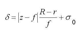
где в линейном приближении:
d – полурадиус пробы, равный , где s – средне квадратичное отклонение, IS – кривая воздействий, xc – координата центра пробы, J – суммарная интенсивность зонда, z – расстояние точки на поверхности объекта от выходной плоскости объективной линзы, f – фокусное расстояние, s0 – радиус сечения зонда плоскостью фокусировки, R – радиус выходного отверстия объективной линзы, |z – f| суть высота объекта, X – область интегрирования, определяемая протяженностью объекта вдоль данного направления. В силу зависимости d от |z – f| кривая воздействий отражает форму объекта, и в силу d = программное обеспечение, развитое для моделирования РЭМ изображений, (напр. Joy’s PC Monte Carlo programs, Casino Monte Carlo Program, SEMLP и пр.), применимо для операций с кривой воздействий.
Источником информации о кривой воздействий могут служить изображения, получаемые при НеДГФ. Разность кривых воздействий, возникающих при разных углах сходимости зондов, описывается выражением:
где I− – разностная кривая, и d1 d2 относятся к 1-й и 2-й сходимости. Введем понятие плоскости нулевой высоты объекта, т.е., плоскости относительно которой измеряется его высота (ПНВО). Очевидно, что если для некоторого сечения объекта Y при формировании изображений, отвечающих разным углам сходимости, d1 = d2, то для сечения Y = 0. Подчеркнем, что кривая воздействий характеризует суммарное воздействие зонда на объект, и распределения интенсивности на РЭМ изображениях характеризуются профилями интенсивности, но что в точках, где идентичны локальные воздействия для зондов, отвечающих разным сходимостям, идентичны также выходы электронов отдачи. Подобные точки можно именовать изофокусными. При наложении кривых воздействий, они пересекутся в точках, расстояние которых от ПНВО равно расстоянию от ПНВО сечения Y, для которого d1 = d2, и если вычитать кривую воздействий, отвечающую одной сходимости, из кривой для другой сходимости, то в изофокусных точках разностная кривая меняет знак или на ней возникают экстремумы. Для РЭМ изображений существуют правила, которые наиболее точно выполняются для электронов отдачи, имеющих энергии » 20 – 50 eV и, соответственно, минимальный свободный пробег в объекте [8]: 1, профили интенсивности на изображениях объекта, отвечающих разным углам сходимости зондов, пересекаются вблизи изофокусных точек; 2, при вычитании одного подобного профиля интенсивности из другого экстремумы разностного профиля или его нулевые значения наблюдаются вблизи изофокусных точек.
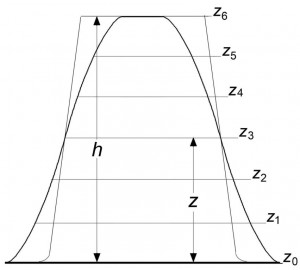
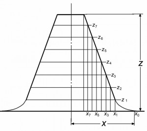
Для сфокусированного изображения, полученного в условиях ДГФ, любое сечение объекта находится в условиях точной фокусировки, и любая точка на профиле изображения может считаться изофокусной. Поэтому при наложении профилей, один из которых сформирован в условиях ДГФ, а второй в условиях НеДГФ, точки пересечения профилей принадлежат сечению, образованному плоскостью фокусировки для изображения, полученного при НеДГФ, что может использоваться для измерений вдоль оси z. Для получения трехмерных изображений объекта по двумерным РЭМ изображениям необходимо: 1, совместить в условиях НеДГФ плоскость фокусировки с ПНВО; 2, получить ряд изображений, перемещая плоскость фокусировки от ПНВО на фиксированные расстояния; 3, наложить изображение, полученное при ДГФ, на изображения, сформированные при НеДГФ. В результате будут определены высоты объекта, его деталей, а также численные значения x–, y–, z-координат отдельных точек. (Процедура определения формы объекта характеризуется рис. 1 и 2.) В силу закономерностей сфокусированных ДГФ картин [8,9] характеристики трехмерного ДГФ изображения наиболее точно отражают форму и размеры объекта, и это изображение может использоваться как исходная модель для восстановления истинных параметров объекта.
Предлагаются следующие этапы определения истинных параметров объекта по его трехмерному изображению-модели: 1, строится РЭМ изображение модели с составом, отвечающим составу объекта, и условиями формирования, повторяющими условия формирования изображения самого объекта [8]; 2, изображение модели подгоняется к экспериментальному изображению объекта путем вариаций её размеров, и 3, размеры, при которых её изображение совпадает с изображением объекта, принимаются за размеры объекта. Т.е., заключительная стадия предлагаемого подхода к идентификации объекта идентична подходам, в которых размеры объекта определяются путем подгонки изображений меры или предполагаемого эталона к его экспериментальному изображению [11]. Однако предлагаемый подход основан не на предположениях о возможном габитусе объекта, а на восстановлении его трехмерного изображения, объективно отражающего этот габитус, применим к объектам самых сложных форм, позволяя избежать ошибок из-за несоответствия между формами мер или эталона и реальных объектов [8,9]. В сочетании с методом дифракции обратно рассеянных электронов (EBSD) [12] предлагаемый подход позволяет контролировать структуру и морфологию объектов, которым отвечают изображения каждой группы.
Контроль массивов (после установления связей между характеристиками объектов и их изображений) сводится к выявлению на РЭМ микрофотографиях изображений разных типов, и темп контроля приблизится к темпу межоперационного контроля в микроэлектронике, т.е., будет отвечать требованиям не только выходного, но также межоперационного контроля.
На сегодня решено большинство технических проблем, необходимых для реализации предлагаемого подхода, разработаны: контролеры сферической аберрации [13] и устройства для управления сходимостью зонда [14], существуют системы для сопоставления изображений, отвечающих разным сходимостям [13]. Поэтому для реализации метода достаточно встроить в микроскоп механизм, контролирующий совмещение плоскости фокусировки с ПНВО и её последующие перемещения на заданные расстояния. Обеспечение РЭМ устройством по типу устройств, известных в сканирующей зондовой микроскопии [15], в которых игла кантилевера является датчиком, а отраженный лазерный луч используется в системе регистрации, технически решаемая задача.
Список литературы
- M.S. Dresselhaus, Yu.-M. Lin, O. Rabin et al. Nanowires. in Springer Handbook of Nanotechnology. Ed. B. Bharat. 113 – 160. (Springer 2007).
- C.M. Sayes, D.B. Warheit. International J. of Nanotechnology, 5, 15-29, (2008).
- M.G. Bawendi, K.F.Jensen. USA Patent No 6,774, 362. Invention Control (2004).
- Nanotechnology: Consequences for Human Health and Environment. Eds. Hester R.E.,
Harrison R.M. // RSC Publishing. 2007. 149 P. - С.К. Максимов, К.С. Максимов. Российские нанотехнологии, 4, № 3-4, 59 – 70, (2009).
- С.К. Максимов, К.С. Максимов. Нанотехника, 18, 5-12 (2009)
- С.К. Максимов, К.С. Максимов. Письма в ЖТФ. 35, № 5. 58 – 65 (2009).
- J. Goldstein, D. Newbury, D. Joy, et al. Scanning Electron Microscopy and X-Ray Microanalysis. (Kluwer Acad. & Plenum Publ., N.Y., USA, 2003).
- Liu J. High resolution scanning electron microscopy. // In Handbook of Microscopy for Nanotechnology, Eds. Yao N., Wang Zh.L. 325 – 360. (USA, Kluwer Acad. Publ. 2005).
10. К.С.Максимов. Известия вузов. Электроника. № 2, 69 – 73, (2009).
11. Ю.А.Новиков, А.В. Раков, П.А.Тодуа. Труды ин-та общей физики им. А.М. Прохорова. 62, 3 – 12, (2006).
12. D. Dingley. J. of Microscopy, 213, 214 – 224 (2004).
13. T. Kawasaki, T. Yoshida, Y. Ose, H. Todokoro. USA Patent No 7,199,365 Electron beam apparatus with aberration corrector (2007).
14. Kitsuki, K.Aoki, M.Sato. USA Patent. No 7,442,929 Scanning electron microscope (2008).
15. B. Bhushan, O. Marti. Scanning Probe Microscopy – Principle of Operation. Instrumentation and Probes, in Springer Handbook of Nanotechnology. Ed. B. Bharat, 239–278 (Springer 2007).


 English